The scintillation light produced inside the HELYCON detectors is guided, through optical fibers, to PhotoMultiplier Tubes (PMT). The produced analogue waveforms are currying information concerning the time of arrival and the particle intensity of the shower front. This information, provided by an array of HELYCON detectors, is used to determine the orientation and location of the shower as well as to estimate the energy of the primary particle.
The Readout electronics, designed to process the signals of the HELYCON detectors, utilize an extension of the Time-Over-Theshold technique (multi Time-Over-Theshold m-ToT) in order to extract accurately the timing and charge information. The prototype HELYCON Readout electronics board supports up to five independent analog inputs, each one dedicated to an individual HELYCON detector. The input signals are compared to six predefined (remotely adjustable) thresholds and the corresponding times of the PMT waveform-threshold crossings (both leading and trailing edge) are digitized with an accuracy of 100 ps by a High Performance Time to Digital Converter chip (HPTDC). The pulse arrival time is estimated very accurately as the time that the analogue signal exceeds a typical threshold value, while for the pulse charge estimation a multi Time Over Threshold (m-TOT) technique was developed, offering an accuracy better than 10%. This technique has also been considered to process the electronic waveforms of the Optical Modules of an underwater neutrino telescope, since that would reduce the complexity of the necessary off-shore electronics, minimizing thus power consumption and maximizing reliability.
In order to evaluate the charge estimation resolution and efficiency of the m-ToT technique, extensive air showers data, collected by an array of HELYCON detectors, were digitized using a high sampling rate oscilloscope. The digitized waveforms were further off-line analyzed in order to simulate the m-ToT operation. That is the simulation of the m-ToT electronics operation concerning the time evaluation when a waveform crosses a set of predefined Voltage thresholds (namely 3, 10, 20, 40, 70 and 100mV).
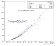
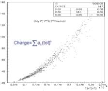
Several algorithms have been developed which estimate the integral (total charge) of the waveforms using the measured time over threshold intervals. As an example it has been shown that the sum of the time intervals, when the waveform is above the preselected thresholds, is a very good estimator of the charge.
The top Figure demonstrates the functional relation of the sum of time-over-thresholds with the actual waveform charge, which can be parameterized as a simple polynomial and can be used as calibration curve to estimate the total waveform charge using the sums of the above time intervals.
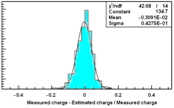
As it is shown in the middle Figure, the relative deviation of the m-ToT estimated charge, from the actual accurately measured value, peaks at zero with a spread of less than 5%, when at least the four first threshold levels have been crossed.
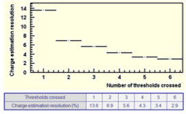
As the number of crossed threshold levels increases, the resolution in estimating the waveform’s charge gets better.
The case with the worst accuracy, of the order of 13% , corresponds to very small pulses, when only one threshold is crossed, whilst the best accuracy (large pulses) is of the order of 3% when all six thresholds have been crossed, as shown in the bottom Figure.
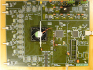
The 1st generation of the HELYCON ReadOut electronics was functionally designed by the Physics Laboratory of HOU whilst the implementation to a stand alone board was designed and manufactured by the Instrumentation Lab of NCSR Demokritos. A 2nd generation of these electronics, following the same functional specifications, are currently under construction (implemented in ASIC) by the Electronics and Computer Engineering Department of University of Patras.
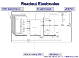
As shown in the schematic, the 1st generation Readout board features 5 independent signal inputs. The signals are amplified and then pass through a set of comparators. The outputs of these comparators are driven to the heart of the system, which is a High Precision Time to Digital Converter developed at CERN. The TDC’s outputs are then led along with the GPS signal to the FPGA (a Xilinx one) which supports filter algorithms, trigger logic and performs the event building algorithms.
The communication between the FPGA and the hosting computer is handled by a Cypress USB Controller. The HPTDC has an accuracy of 25ps with 8 channels or 100ps with 32 channels. The outputs of the HPTDC is the times the input pulses cross the 6 programmable thresholds in either direction (leading and trailing edge).
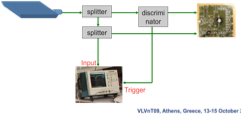
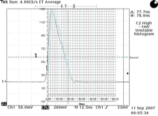
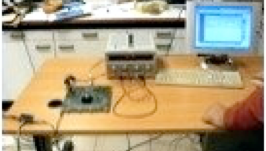
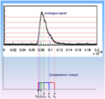
The Readout board has undergone extended testing aiming at determining the optimal functional parameters and to evaluate the operational performance. The performance of these electronics was compared to the digitization of the same input pulses by a fast, high accuracy digital oscilloscope. The signals from a HELYCON detector were split, driven simultaneously to the Readout board and to a high precision Tektronix oscilloscope. In the picture a pulse is shown as it was digitized by the oscilloscope (black line) and reconstructed (green line) using the times when the waveform crossed the predefined threshold (green dots).

 As the number of crossed threshold levels increases, the resolution in estimating the waveform’s charge gets better.